The RAM expansion I’ll talk about in this post is this one, designed by PeteAU with improvements by Mathesar, over at the English Amiga Board. When fully populated and with the use of a Gary adapter, it is capable of adding 1.5MB of slow RAM and 512k of chip RAM to an A500. If you don’t need/want the chip RAM part you only have to use the Gary adapter and connect two pins on it with corresponding pins on the expansion board. No cutting of traces at all!
To add the chip RAM part as well, in addition to needing the Agnus 8372A or later (which can address 1MB of chip RAM), it is also necessary to cut the trace between the lower two pads of JP2. Then solder a wire to the middle pad and connect over to the Gary adapter. Quite simple.
That’s all well and good, but the Rev 3 A500 doesn’t have a JP2 jumper! I tried finding info on how to go about doing this on the Rev 3 board but the original forum thread didn’t have any instructions that I could find. And it’s hard to find anything meaningful otherwise on google since the name of the expansion is so generic. So I came up with my own solution. It’s likely that there’s a better solution but it works.
What JP2 does on the Rev 5 and 6a boards is that it connects the Agnus pin 59 (A19) to either pin 52 (A23) or pin 47 (A19) on the CPU depending on which pad is connected to the middle one. By cutting the trace between the bottom two pads A19 gets isolated and isn’t connected to anything. With this memory expansion it is instead connected directly to the Gary adapter.
So instead of using a jumper, a corresponding trace on the Rev 3 board for A19 needs to be found and cut/isolated, then connected to the Gary adapter. By using a multimeter I found pin 59 on the Agnus chip, by confirming it was connected with pin 52 on the CPU (the default configuration on rev 5 & 6a). This pin will also be connected to pin 39 on the Gary chip.
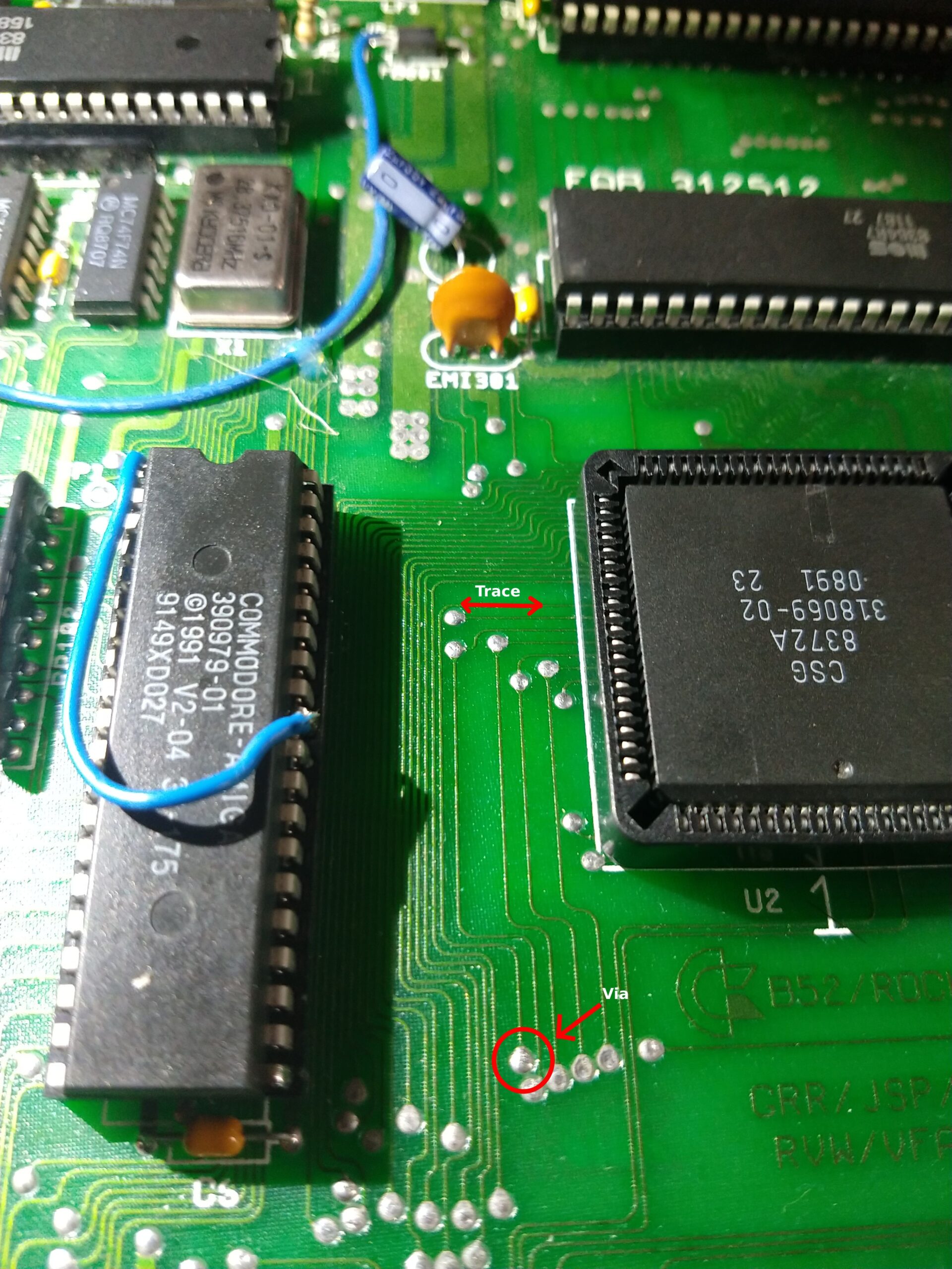
Conveniently on the Rev 3 board, pin 59 has a trace on the top side right in front of the socket that is quite accessible. And it even has a via close by leading to the underside of the PCB which we can solder the wire to. So that’s it, we have to cut this trace, then solder a wire to it which we connect to the Gary adapter.
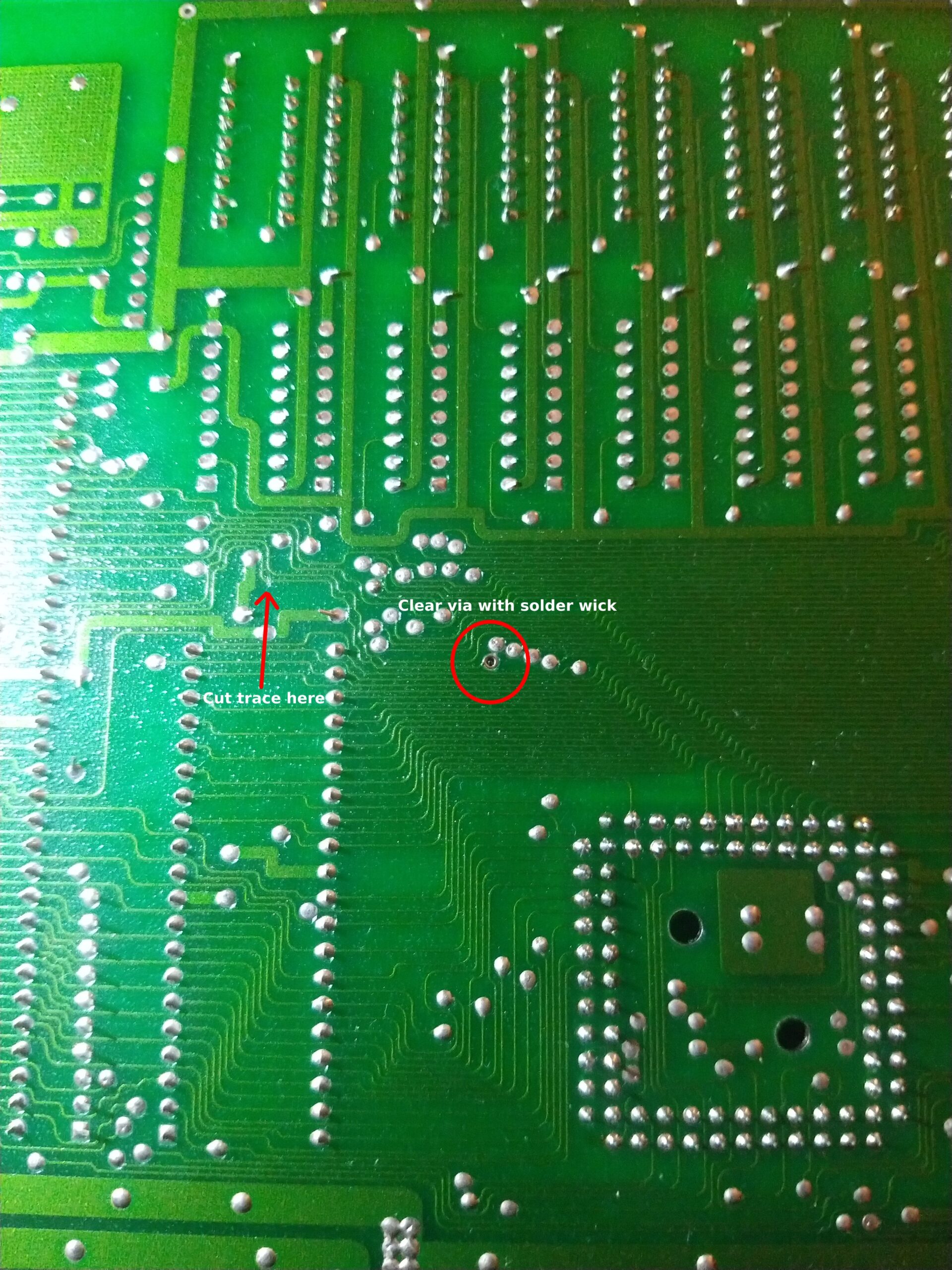
Once the right trace has been located, remove the solder from the via and flip the board around. Then follow the trace a bit further where it’s less cramped and cut the trace there.
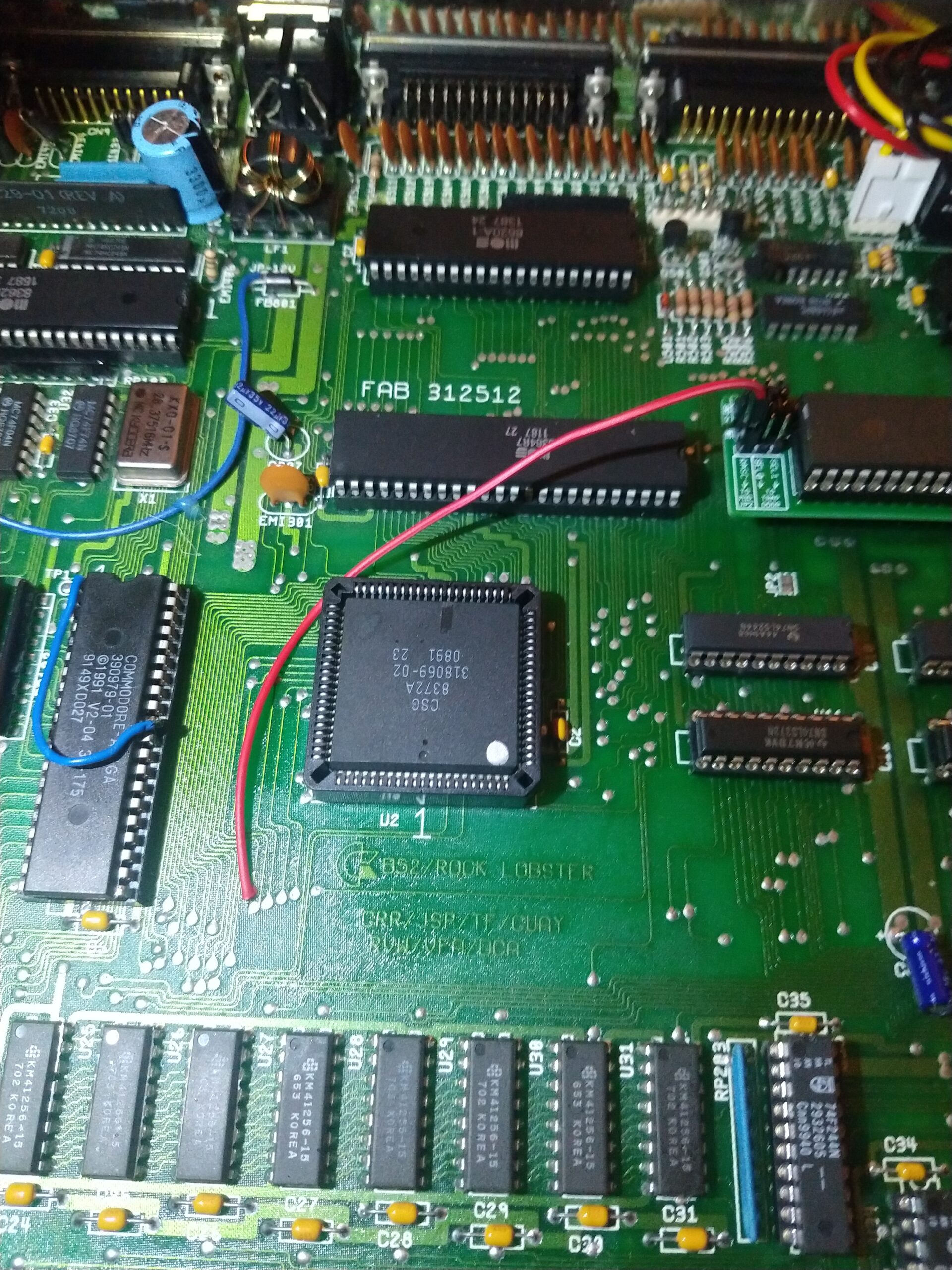
Now it’s only a matter of soldering the wire like so.
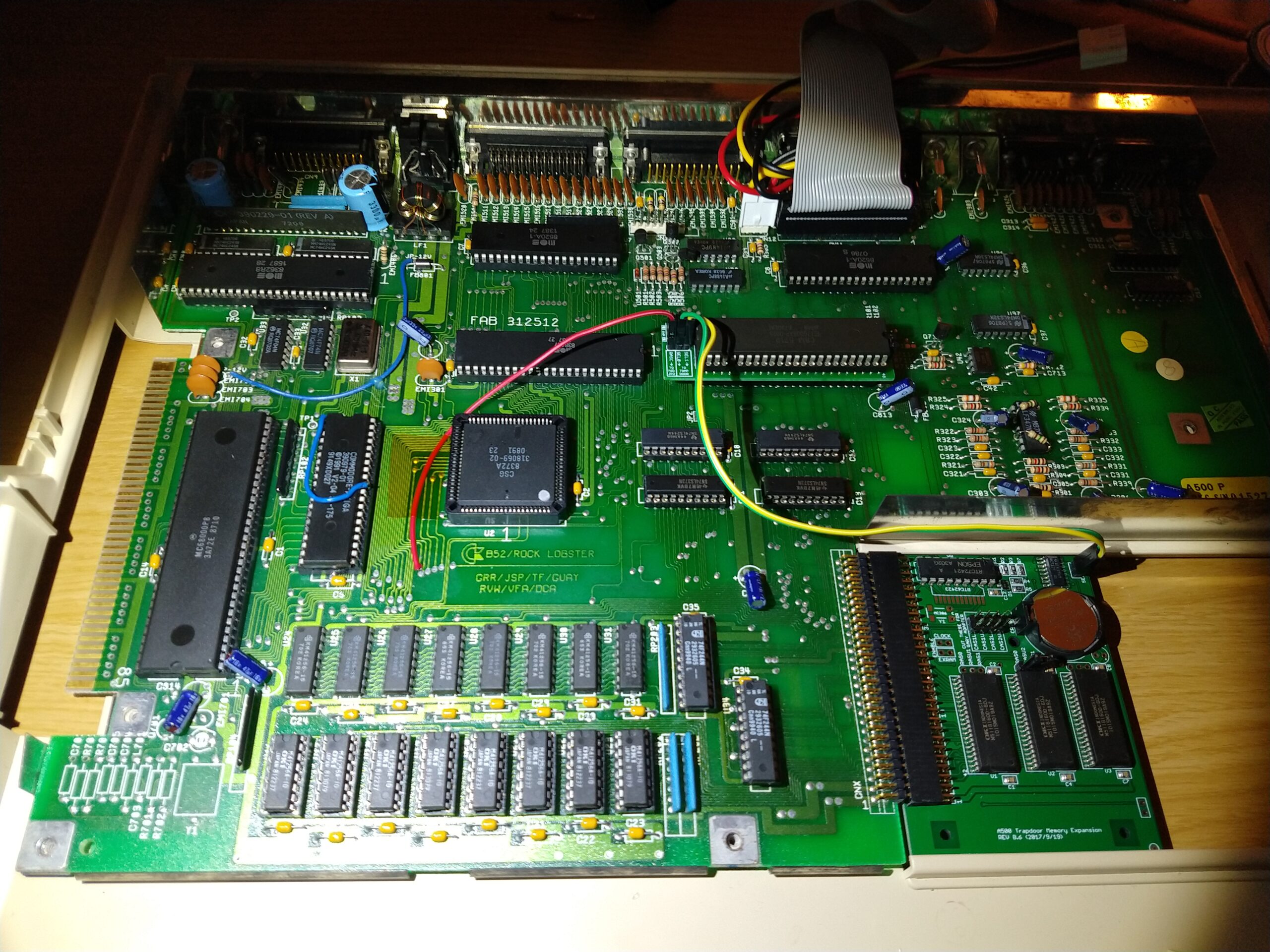
If you haven’t already done so, socket the Gary chip into the adapter and install it. Then install the expansion board into the trapdoor slot and connect the pin headers of the adapter and the board together.
So that was that. Did it work?
Condensed instructions
Prerequisites
- Agnus 8372A – to be able to address 1MB of chip RAM. In PAL systems you’ll need to isolate pin 41 with some tape or similar, otherwise it boots up the Amiga in NTSC mode. You can see I have done this in the pics above.
- PeteAU’s trapdoor memory expansion – The one I used was Rev B6.
- Jump wire (with female connectors).
Instructions
- Locate pin 59 on the Agnus chip either by counting or by checking continuity to pin 52 on the CPU, and pin 39 on Gary. Both these should be connected to pin 59 by default.
- Locate the trace right in front of that pin on the top side of the PCB. It’s between the Agnus and Kickstart ROM sockets. Follow the trace to the via that leads to the underside of the PCB. Check continuity between the via and pin 52 on the CPU to make sure it’s the right one!
- Remove the solder from the via and flip the PCB over.
- On the underside of the PCB, locate the now cleared via and follow the trace a bit further to an area where there’s more space around it, and cut the trace. Check that there’s no continuity from the via to pin 52 on the CPU to make sure it’s cut. Flip the PCB over again.
- Grab a jump wire with female pin header connectors and cut to appropriate size. Solder the naked conductor end to the via hole, and connect the other end to the pin header on the Gary adapter that says “TO MID JP2”.
Done. Of course you have to configure the jumpers on the Gary adapter appropriately. To use the full 2MB put all the jumpers to the bottom positions. Plug the trapdoor expansion board in, connect the adapter to the board, and enjoy your expanded Rev 3 A500!
Links
- A500 trapdoor memory expansion: free design – Original thread on English Amiga Board.
- Amiga 500 512k/2MB Memory Expansion + RTC – Product page on AMIGAstore.eu, where I bought mine. Choose the 2MB version obviously.
- Amiga 500 chipram expansion with no motherboard modifications – This is a blog post about the more traditional way of expanding chip RAM on a Rev 3 board, by using a normal 512k trapdoor expansion board and turning it into chip RAM. While this post is about not modifying the board at all it did have a lot of useful info.
- Photo of backside of Amiga 500 Revision 3 board – If you’re gonna do the traditional chip RAM mod described in the above link but don’t care to design custom adapters like that blog post, this photo courtesy of Amiga Hardware Database has an example of the mod done by cutting traces. At least the switching CPU pin 52 -> 47 part. Look on the right side where the CPU is and you’ll see the cut trace and a wire going to pin 47 from it.