I’ve always thought the Game Boy Pocket was the sleekest looking model of the Game Boy line. Even after the Game Boy Color came out with its undeniably sharper looking color screen, I thought the GBC itself looked quite bulky and ugly in comparison. And apparently I’m not alone in thinking this, because over the last couple of years there have been several projects to recreate the GBC so it fits inside a GBP shell. I decided to build one of these ultimate Pockets for myself.
The board I decided to use for this build is the excellent SZ-POCO by skimzor. There are other boards available, such as the Game Boy Pocket Color by MouseBiteLabs and the Pocket Color by N64-Freak which all have their own strengths. Originally people would take a GBP bottom half and a GBC top half and Frankenstein a board together out of both, but with all these custom board solutions available I’d really not recommend that route today.
My main reason for going with the SZ-POCO was honestly just because I loved the blue color. I also like that it keeps the GBC IR diodes by placing them where the contrast wheel would go on the GBP. The GBC doesn’t use a user-adjustable contrast wheel anyway so I liked this solution a lot. This board also only supports IPS displays (in fact, specifically only the OneChip Q5 IPS Color display) so it does not require you to add the parts that is only for driving the original display, slightly simplifying the build.
I slowly began to amass the needed parts for the build, and had pretty much everything except for a donor GBC. I had two GBCs in my collection but I did not want to destroy something that is working just to make something a bit more shiny. That just feels wrong to me. So I started looking for non-working boards and consoles online. To my surprise, non-working Game Boys go for quite a bit of money these days, not being that much cheaper than a working one. Most likely because people are fixing them up and putting them in a nice aftermarket shell with an IPS display to resell. I bid on an auction for three non-working boards in rough condition, but I got outbid and it ended at over $120. $40+ for a non-working bare PCB! Plus shipping! This is crazy, I thought. I can buy a complete non-working unit for less than that from Japan. So that’s what I ended up doing.
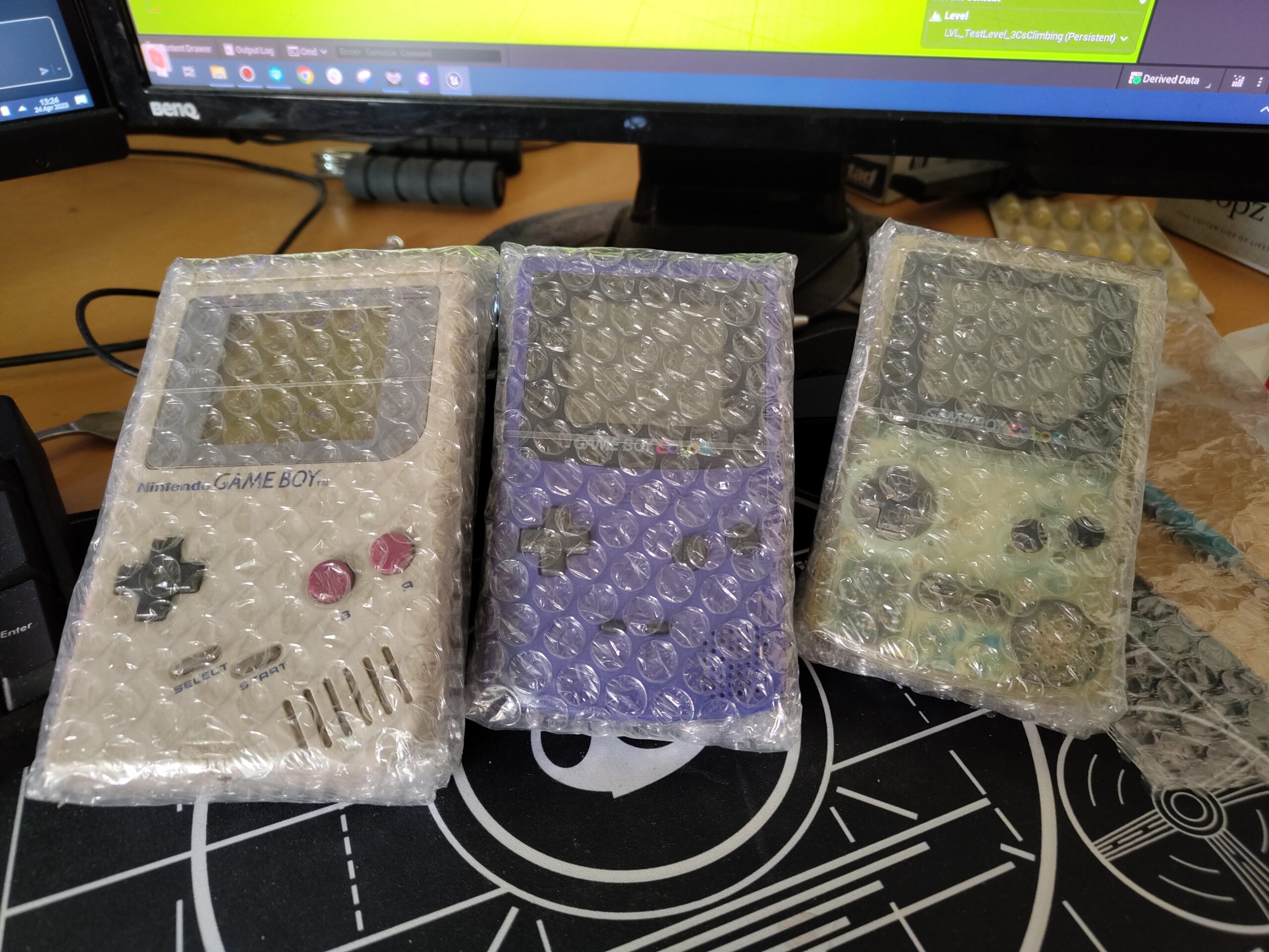
The package arrived a week or two later. I had ordered two GBCs and one original Game Boy. The extra GBC and GB will be for future projects was my thinking. The consoles were very carefully packaged and arrived as described. The cheapest of the GBCs was visibly damaged from battery acid in the listing, but I took a chance on it anyway. It turned out to be way worse than I expected however.
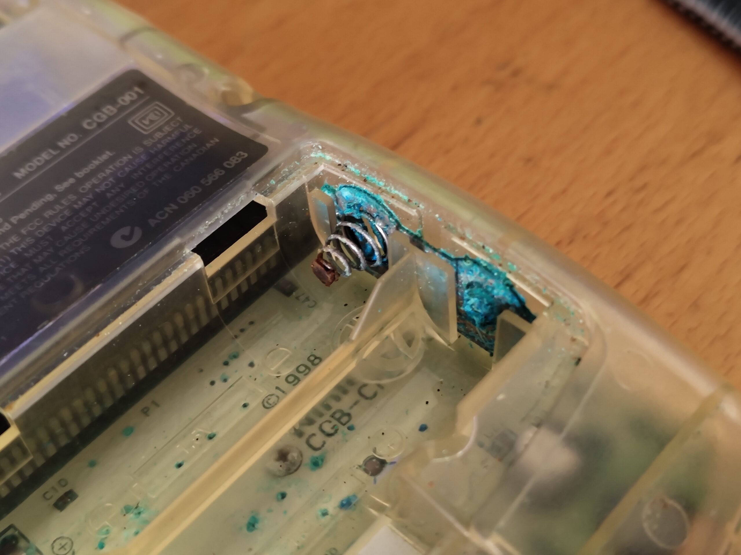
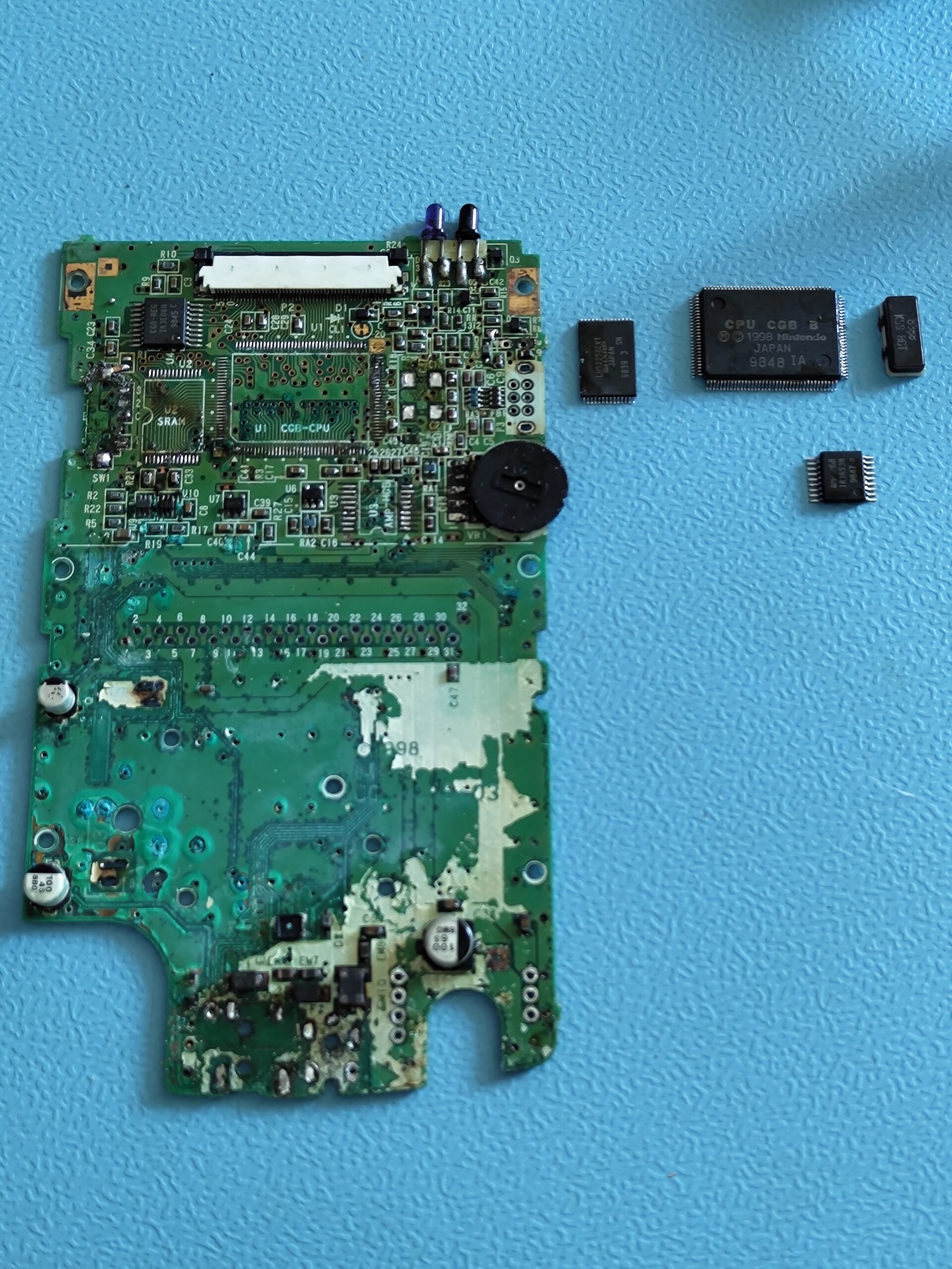
Opening it up I was shocked at the state it was in. This was without a doubt the worst battery damage I’d ever seen. Luckily the top part of the board, while clearly corroded, wasn’t as bad as the bottom. This gave me some hope that it could still be salvaged, although it’d be risky to use the parts without being able to test the functionality before.
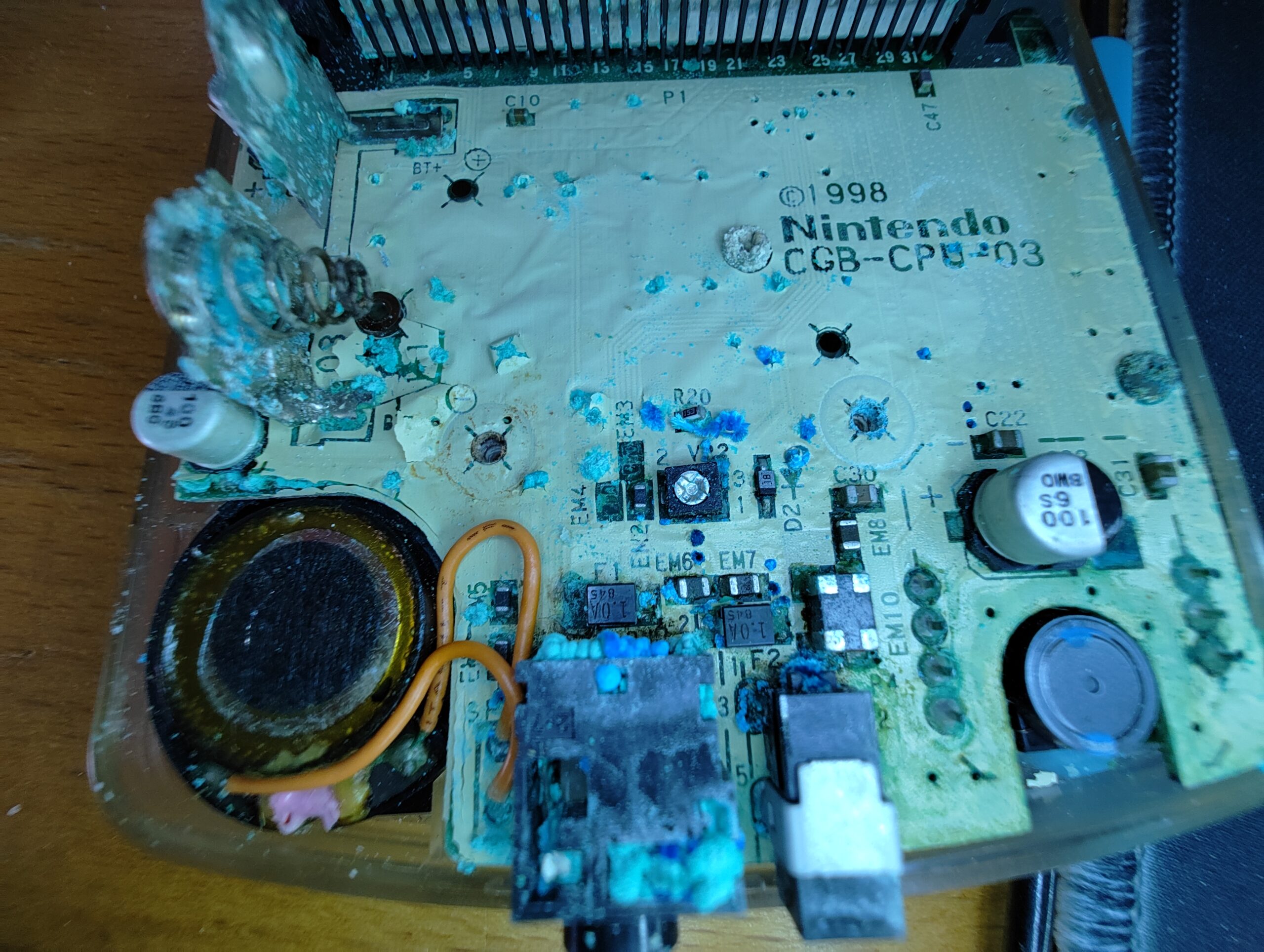
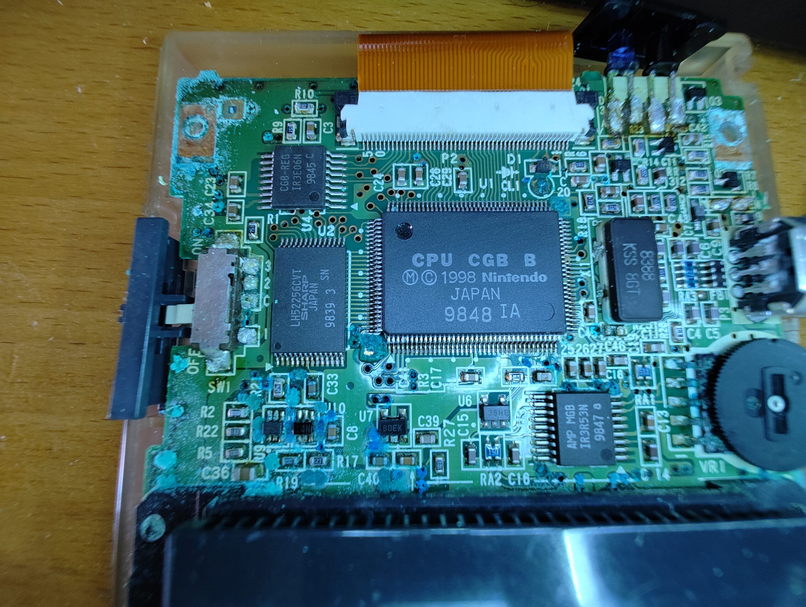
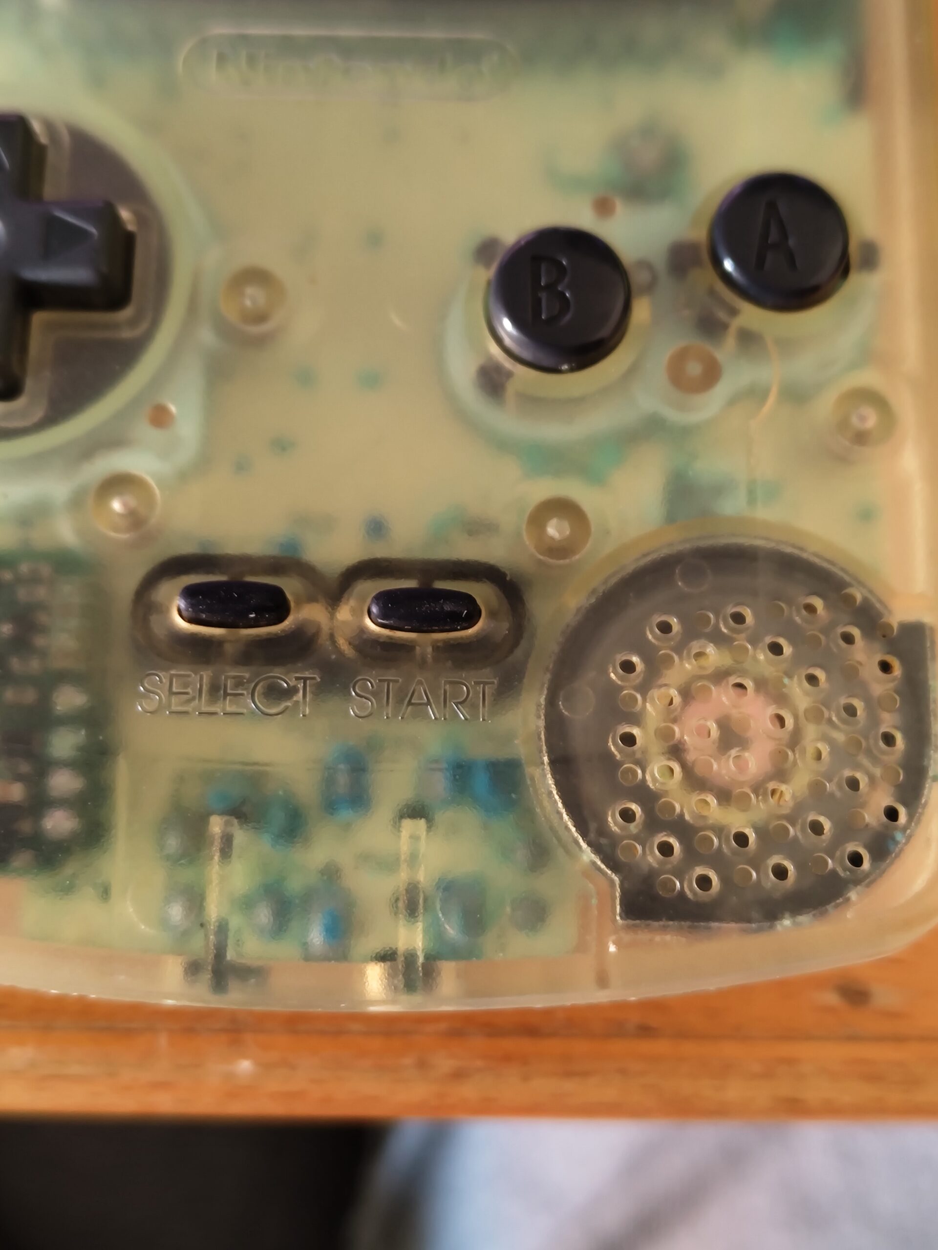
There was no way I was going to be able to test this board though. It was too far gone. Even if I had wanted to repair the traces necessary to make it work it wouldn’t have been possible. Cleaning the board up with vinegar caused the white coating to flake off, and some smaller components along with their pads also came right off. But again it was only the bottom part of the board. The top part cleaned up reasonably well.
I decided to risk it and use this board for the build. I really wanted to give this poor GBC a new life. I took off all the ports, the power regulator board, and the cartridge slot and cleaned them thoroughly, and surprisingly they mostly cleaned up very well. I ended up buying new replacement DC jacks however, but I wasn’t able to find any replacement audio jacks. I left the rest of the components on there and let the project sit until my summer vacation when I would have more time for it.
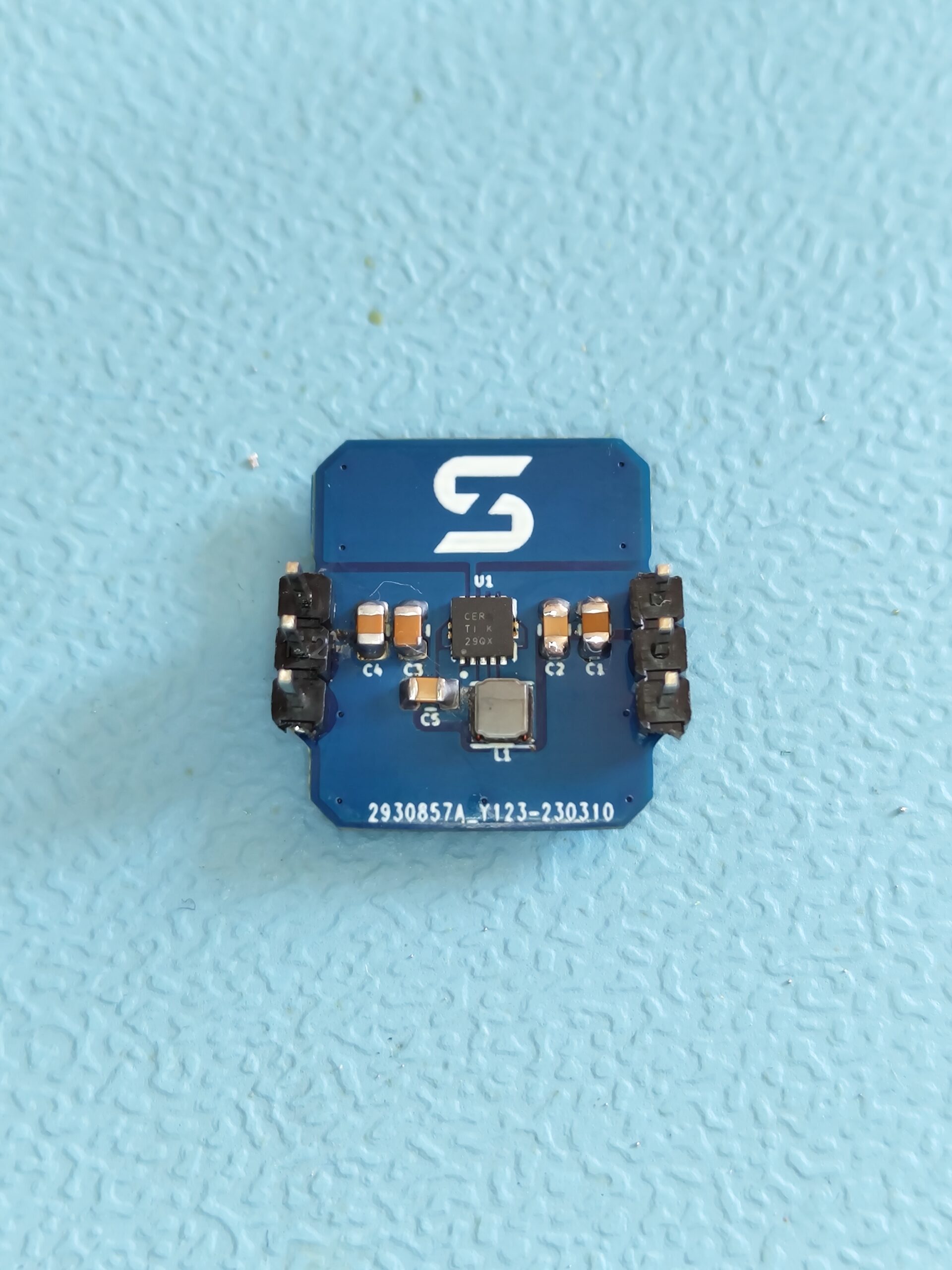
Vacation rolls around and I decide to bust out the soldering equipment and get started one day. I start by building the custom power regulator board that is supplied with the SZ-POCO. I don’t have a hotplate yet unfortunately, and since the main chip is a QFN package I can’t possibly solder it with a soldering iron. Instead I used my hot air station to solder that chip and the inductor on. It seemed to work and looked decent enough.
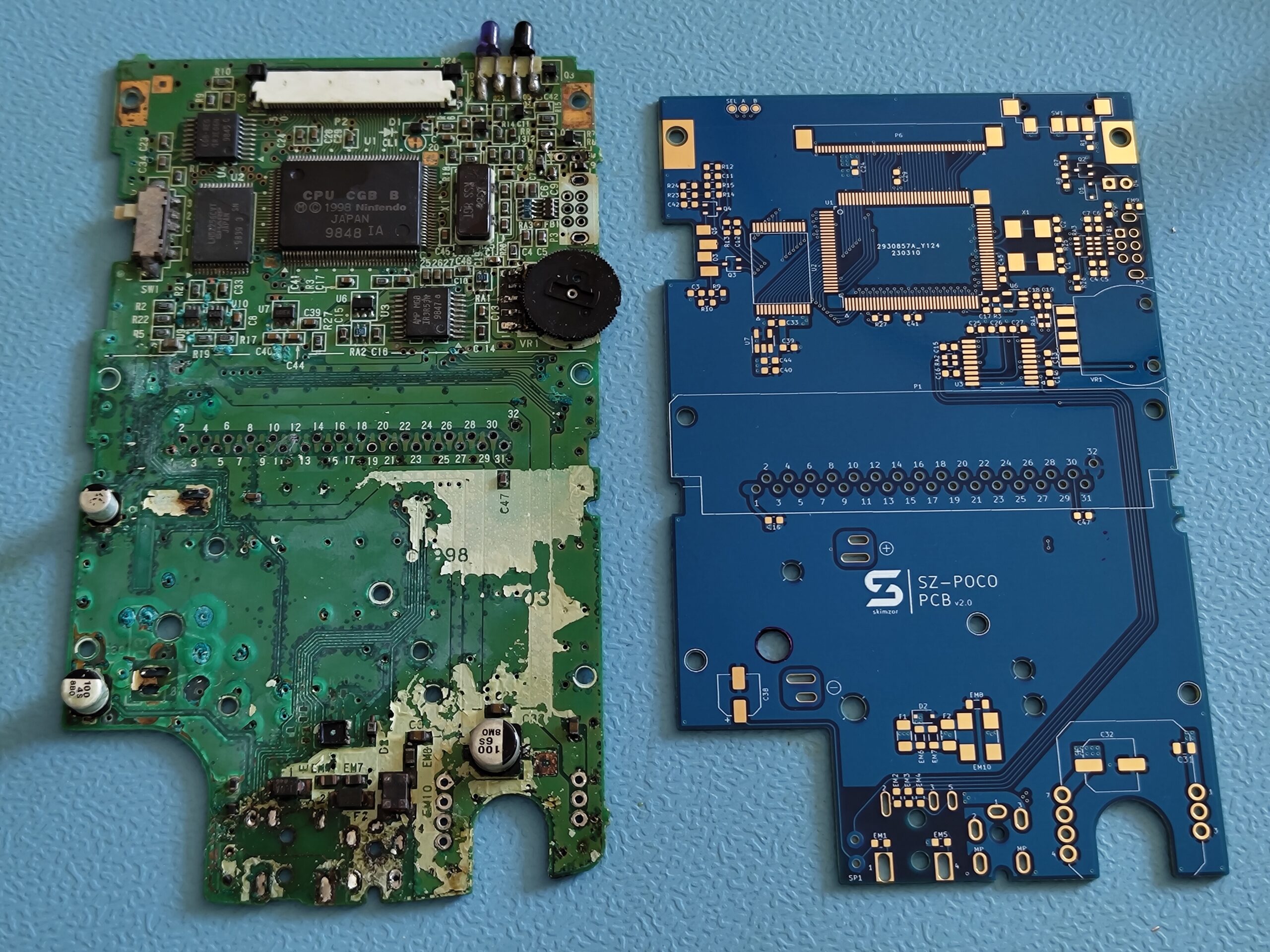
Next up I take the chips off the old board and solder them to the new one. This goes surprisingly well. While I had practiced a bit beforehand on an old Ethernet PCB, this is my first real project with surface mount components.
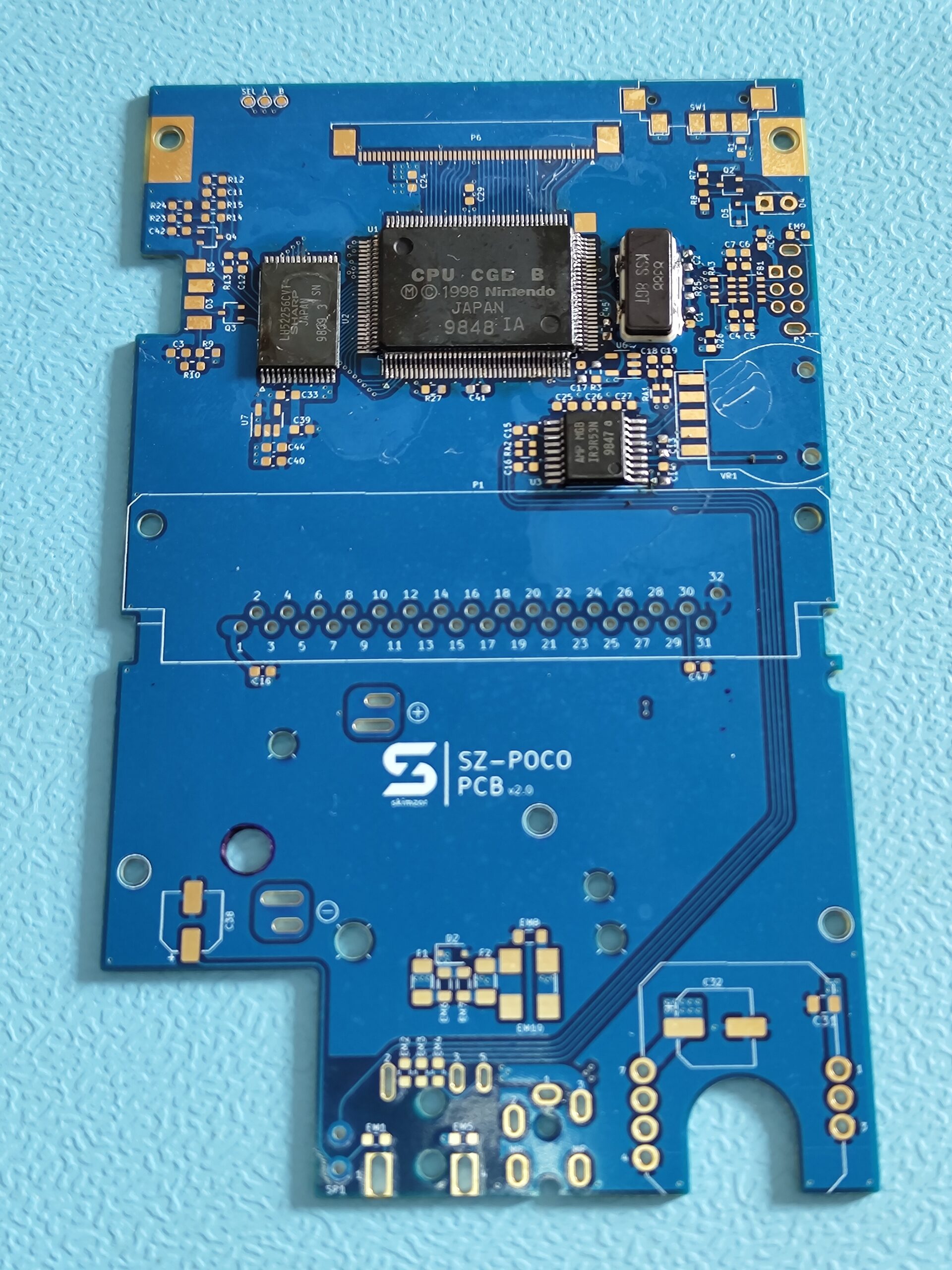
Next I solder the screen ribbon connector on. Rather than take the one from the old board I had bought brand new ones as they’re readily available. After this I start with the transistors and voltage regulator etc. And after that I do the small capacitors, resistors and filters. For the caps and resistors I put brand new ones on except for a few (the 1M Ohm and 1.5M Ohm resistors specifically as I didn’t have those values), but for the filters I did not have any replacements. So I had to take the ones that were still on the original board, and the remaining ones from the other broken GBC I bought.
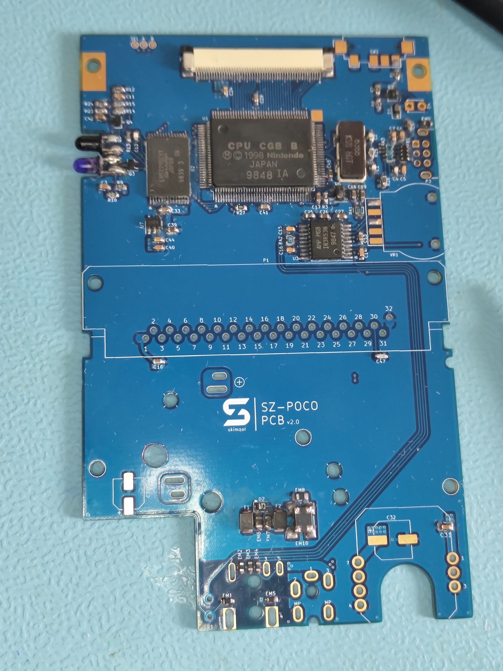
Placing all these tiny components was definitely the most tedious part and took the longest. A lot of that was actually because the replacements I had bought were all shoved together into a single plastic bag causing it to take a lot longer to find the right values than I would have expected. But we’re on the home stretch now. Only some larger components like the power regulator board, cart slot, and the ports left.
After putting all those components onto the board I started cleaning it up and triple checking everything. Everything seemed fine so I decided to connect it to power to test it. So I did and I flicked the switch. Aaand nothing happened. Not even the power LED lit up. At this point I had spent the whole day on the build and couldn’t be bothered anymore. So I took a break and continued the next day.
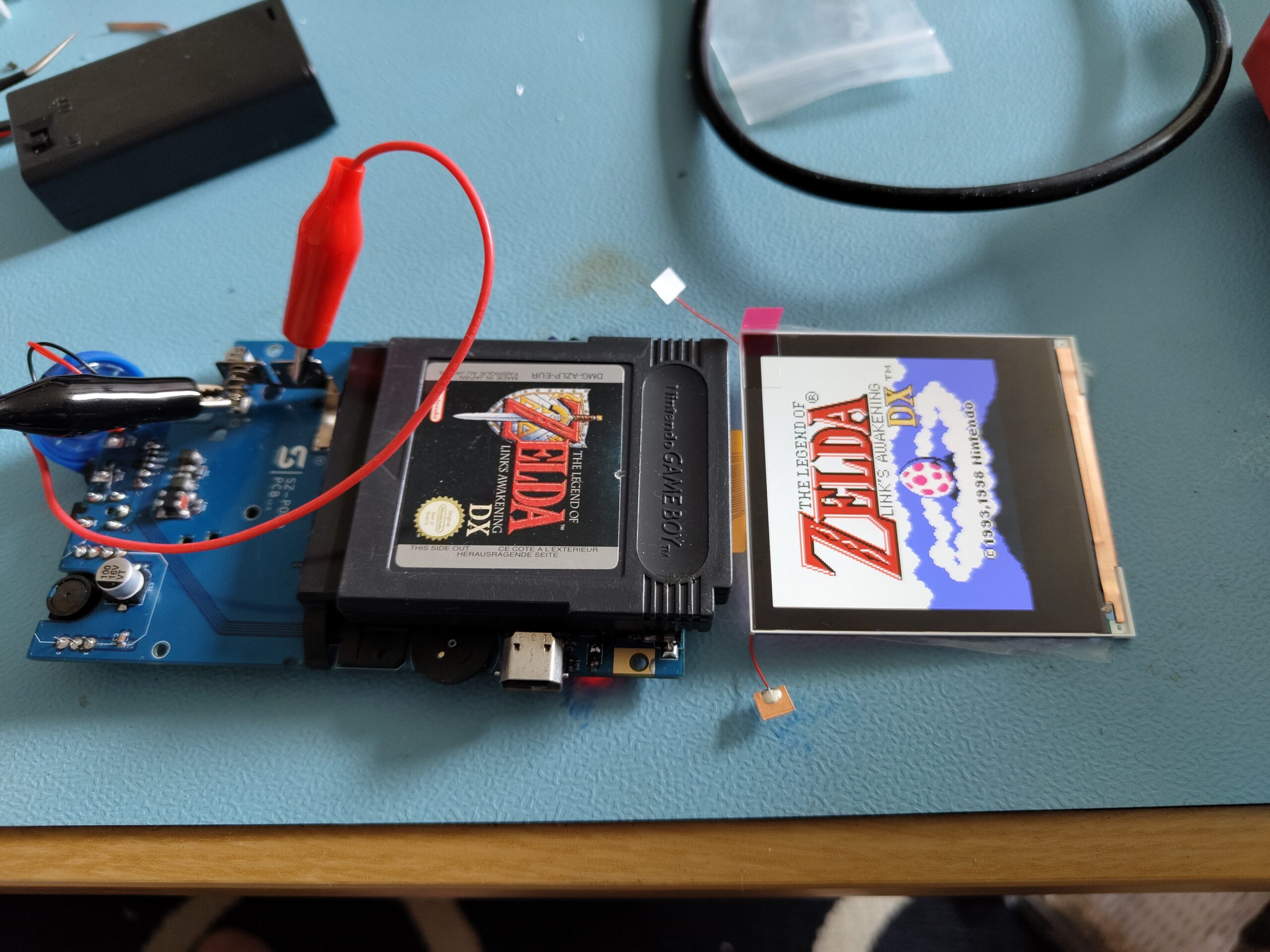
The next day came and only a small amount of troubleshooting was necessary to determine that the custom power regulator board I had built didn’t work. Power came in just fine but nothing came out. Not too surprising I thought, having built it using hot air instead of the recommended hot plate. For now I just took it off and put the original part on there and hoped that worked. And it did. I switched it on and was greeted by the Game Boy startup chime. What a relief I thought. But the troubles didn’t end there.
I connected the screen and switched it on. The screen flickered a bunch and then went black. Reconnected the screen and tried again. Now only half the screen flickered before it turned black. Then the next time it didn’t flicker at all but was just completely black. Thinking I had just killed the $60 screen I was feeling pretty dejected, but I thought at least plug a game in and listen if I can hear it boot. I plugged in Tetris and heard the chime again, then after a second or so the screen turned a solid orange. Okay, so the screen is not dead it seems! But there’s something wrong with the Game Boy.
After playing a bit with it and turning it off and on a few times, eventually the Game Boy logo showed up on the screen! But it was not quite looking how it was supposed to, like it was corrupted somehow.
Eventually with a bit more fiddling the Game Boy logo actually appeared as it should. And then after a bit more fiddling it even booted into the Tetris boot screen text. The only thing I really did here was turn it off and on a few times. It was quite puzzling. After a while it even booted into the game proper but it would crash after a bit.
I should have thought of doing this a lot earlier but I then went to check the schematics and decided to check voltages. The 5V rail was stable and rock solid. But I noticed that the 3.3V supply wasn’t quite right. It was more like 2.4V. Turning it off and on it would change the value it spat out; 2.4V, 1.5V, 2.2V, 0.5V! Something’s not right with this voltage regulator I thought.
I decided to replace the 3.3V voltage regulator (U7) with the one on the other broken GBC I bought. After this the 3.3V supply was rock solid, and the console booted into any game I threw at it just fine!
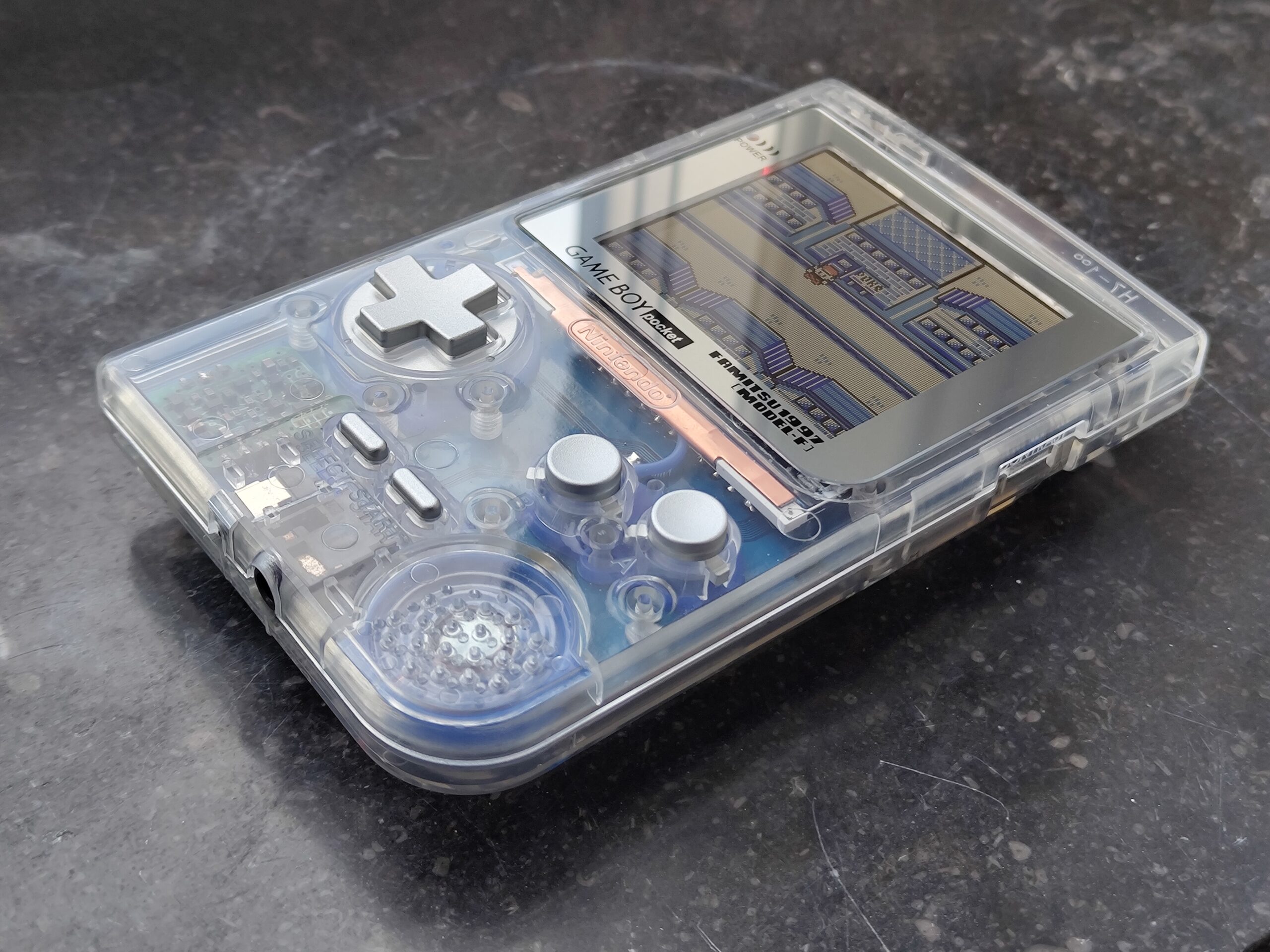
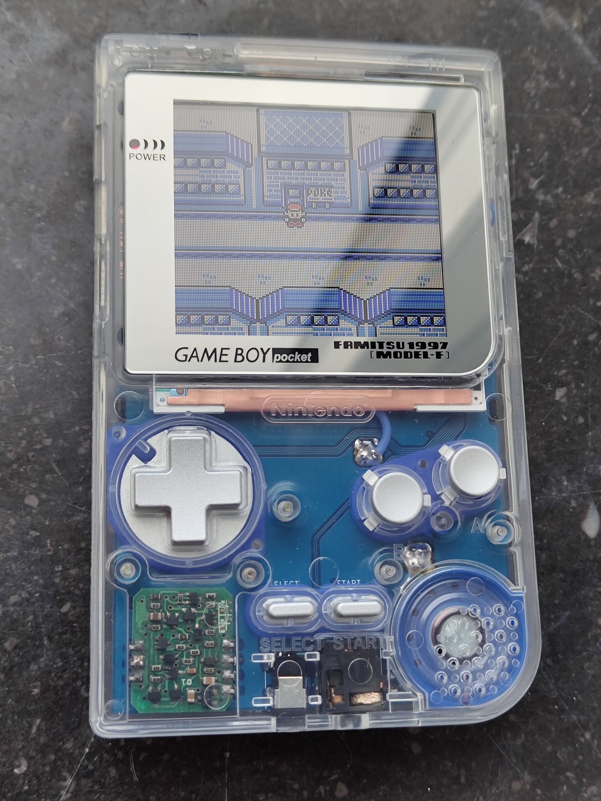
At this point I’m relieved and I go to work on the shell. The shell I wanted to use is the clear shell from Cloud Game Store since it is crystal clear without any frosting or texture. I want this build to be as visible as possible. Since the shell is meant as a replacement for the original GBP and screen, this requires cutting the shell a bit to make the IPS screen fit.
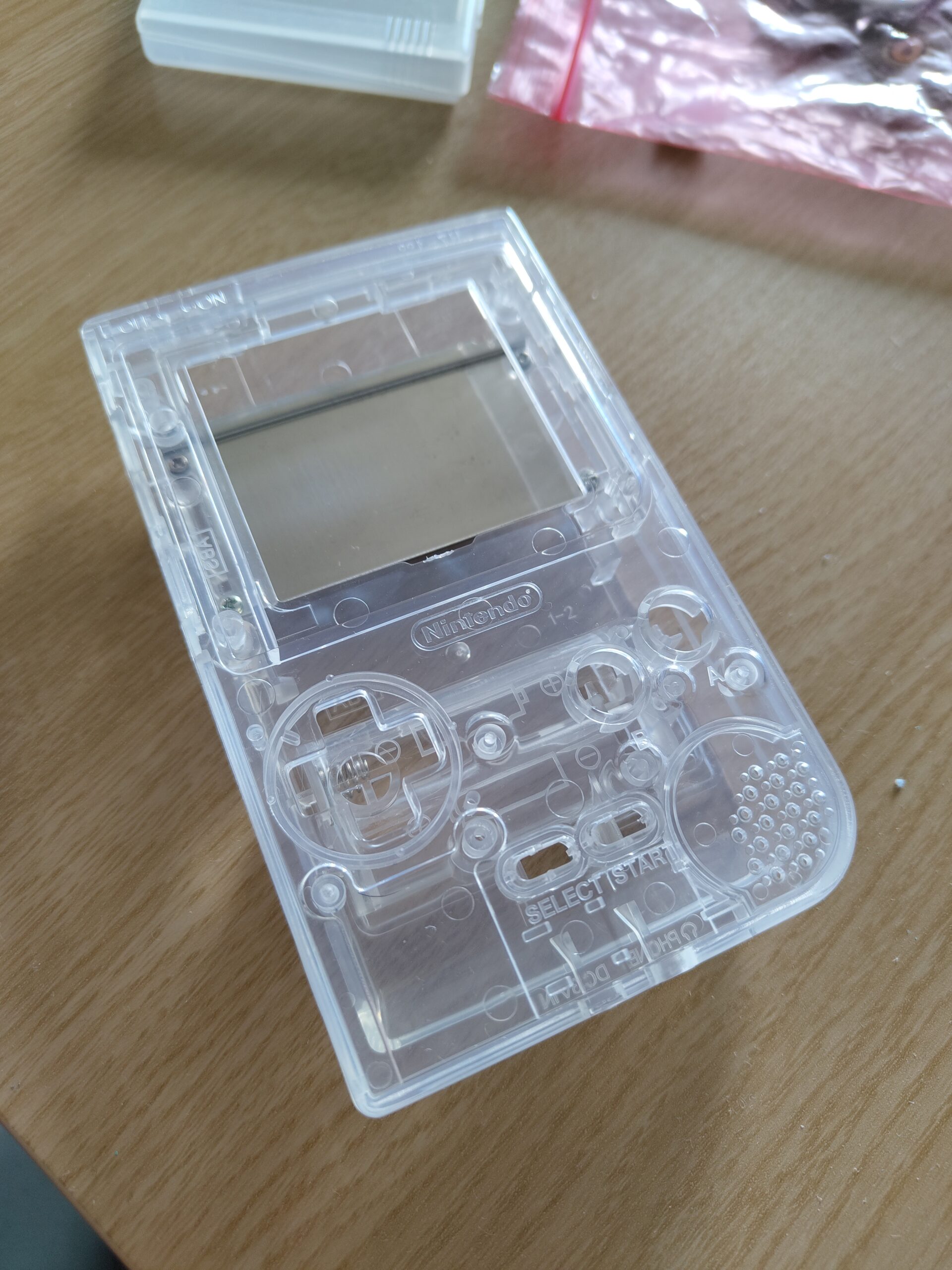
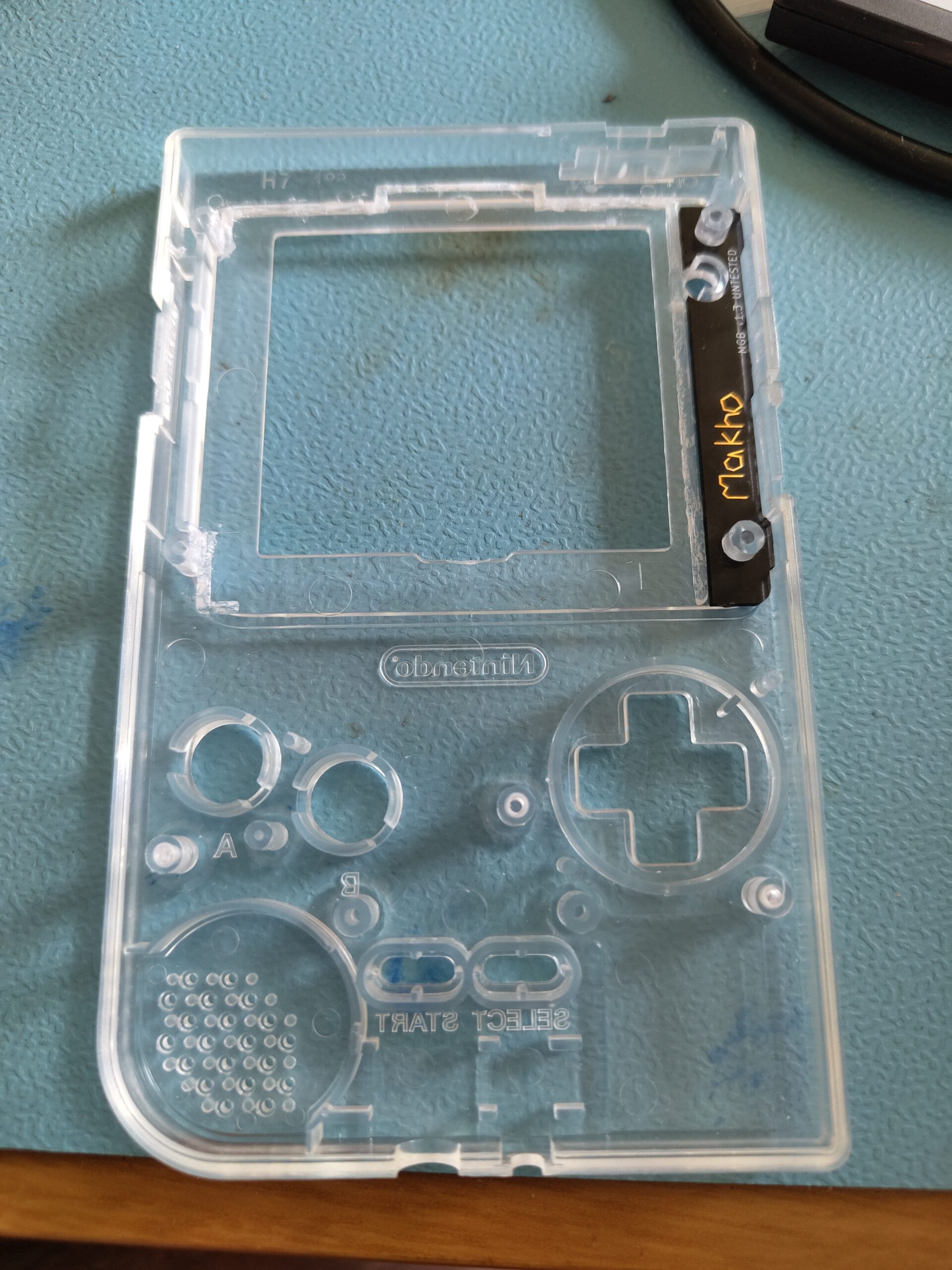
Unfortunately some parts that are necessary to cut off, especially the part along the top that sticks up above the screen lens, are visible on the finished mod. But I think it looks quite alright anyway. There’s probably a better way to cut it to make it look less like cut plastic. I just used some flush cutters to do it.
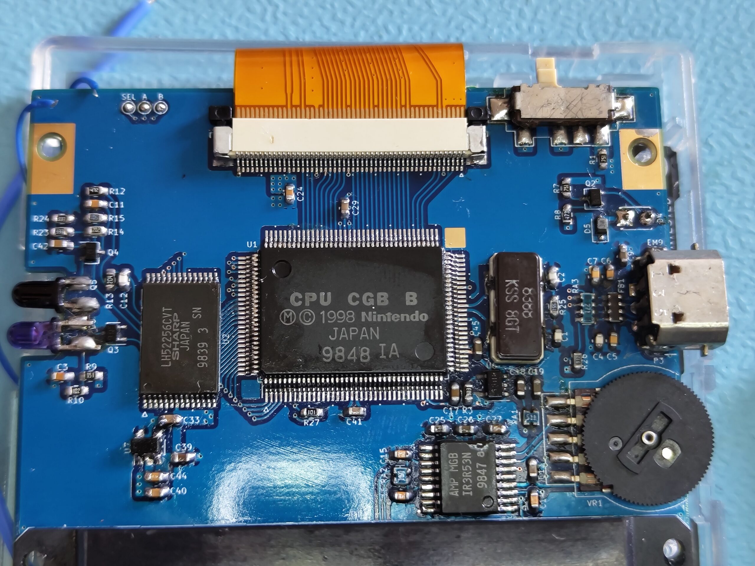
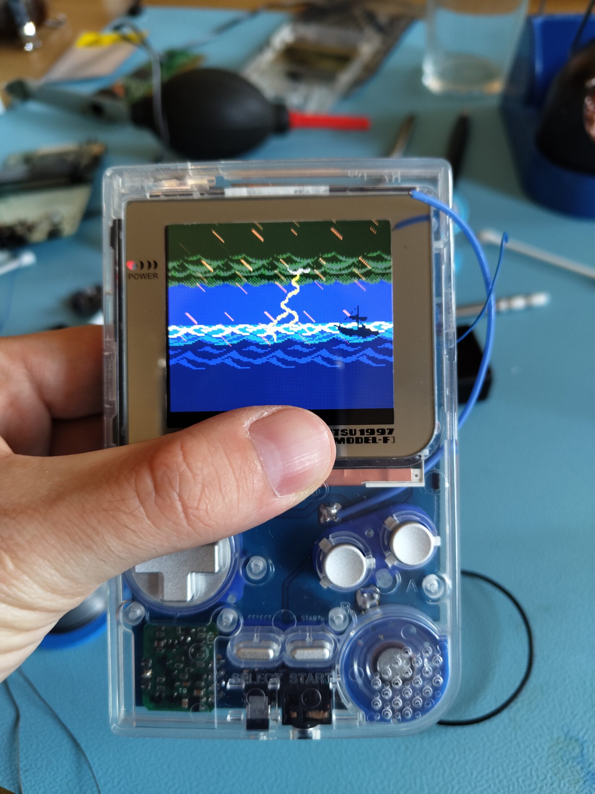
After struggling a bit with the shell and fitting the screen and lens, I start to assemble the rest of the build into the shell. A screw it all together and turn it on. After adjusting the image position with the screen’s built-in OSD it looks quite stunning.
I decided to use a Famitsu 1997 screen lens reproduction and silver metal buttons from RetroCNC. I love that mirror finish on the screen lens and wanted to go for a silver/blue color scheme. The original regulator board kinda ruins that vibe a bit but it will do until I get myself a hot plate and attempt a proper build of skimzor’s regulator board. I did make another attempt at it with the hot air but still no dice. I may also try to source another audio jack since while the original one cleaned up better than I could have ever expected based on its initial state, it isn’t silver-y anymore.
So at this point the build is pretty much done and I’m playing it a bunch throughout the evening. I almost deplete the first set of batteries.
But the troubles don’t end just yet. While playing Tetris, the game freezes on me and throws an error overlaid on top of the playfield. That’s odd I thought, and turn it off and back on again. The Game Boy logo comes on, then it fades to white and stays there. Huh… well it might be a low power issue so I switch out the batteries. Same thing. Re-seat the cartridge? Same thing. Different cartridge?! Same thing. What on earth??
I’m thinking that maybe I need to reflow the solder on the CPU or RAM or something. But at this point it’s getting a bit late and I decide to hold off until next day. In the morning I open it up and do just that. I reflow the solder on both the CPU and RAM, and quadruple-check the work to make sure it’s good. Turn it on. Game Boy logo then white screen. So I double check the voltages. Voltages are just fine and rock solid at what they’re supposed to be.
At this point I’m stumped. Other than taking a shotgun approach and replace components one by one and hope I fix it I’m not sure what to do. Then I remember that I’m on the Gameboy discord server where a bunch of awesome modders hang out, including people who have done this very build. Maybe they have some pointers. So I ask for help there and post pics of my work. Nothing sticks out but I do get some pointers and hints. Several people point out the fact that boot issues are often because the bottom CPU pins might not be connected properly, as they are directly connected to the cart slot. One person thinks the RAM is a bit crooked and suggests that I shift it a bit so it’s more square. I do so, and also the other suggestions but nothing ends up solving the issue.
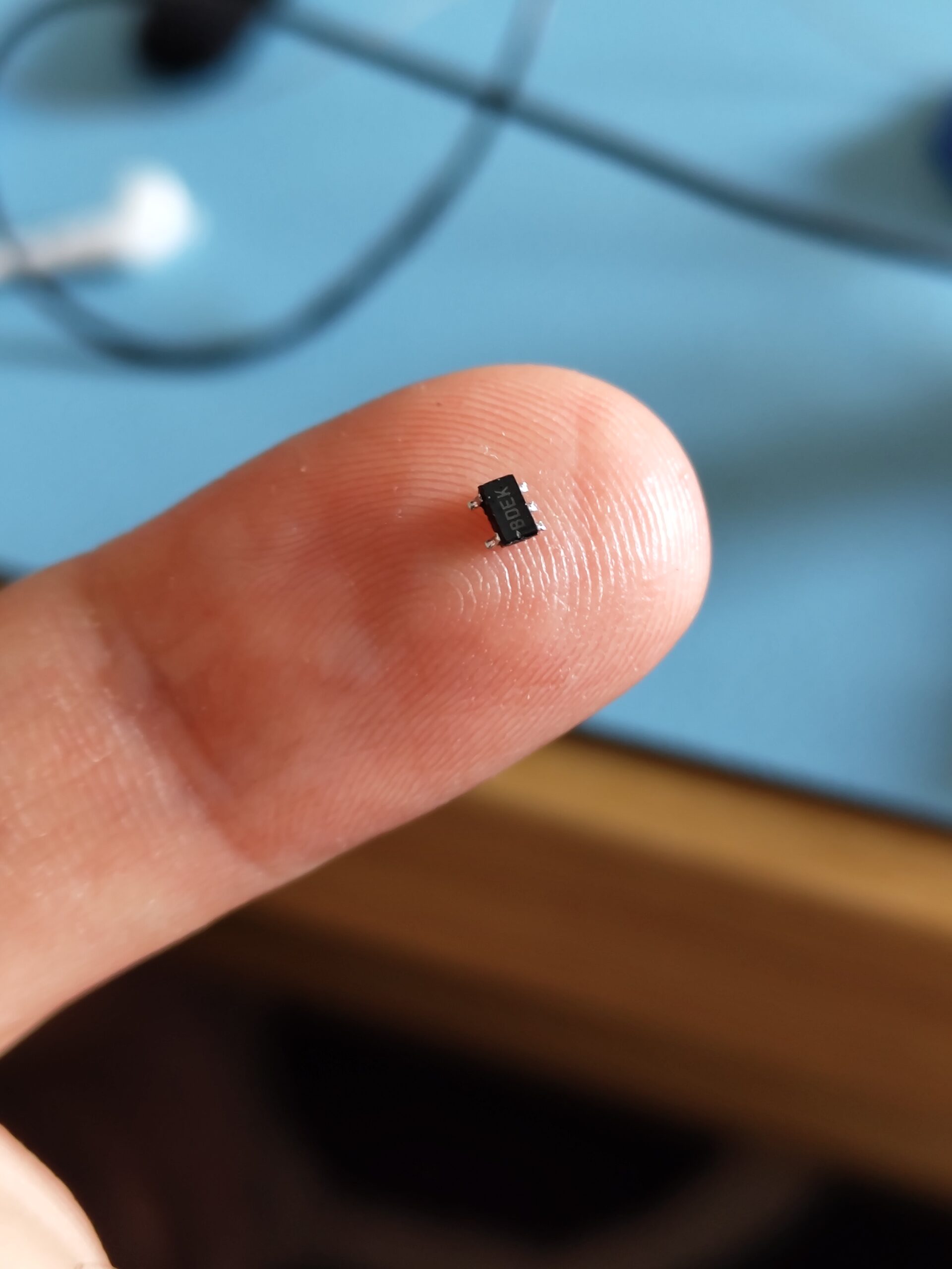
Then none other than skimzor himself suggests that if none of the other things work he thinks it’s because of a bad RAM chip. He’s had the same issue and replacing the RAM has solved it in that case. While that sucks, I do have that other GBC I could take the RAM off of. Since none of the other suggestions have worked I have nothing much to lose. Said and done, I replace the RAM chip, making sure it’s dead centered this time. I clean up and connect the power as well as my Link’s Awakening cart and turn it on. I hear the Game Boy chime, then a second later I hear the game booting up and playing the intro music.
So in the end it turned out the RAM chip was faulty. I’m not sure whether it was faulty from the start, or if the faulty U7 regulator caused it to develop a fault. U7 does supply 3.3V directly to the RAM chip, and while I never saw it go above 3.3V maybe it fluctuating like it did somehow fried the chip. Luckily the RAM chip does have an aftermarket replacement available while none of the other chips do, so for my future GBC mods with the other broken GBC I could get one of those.
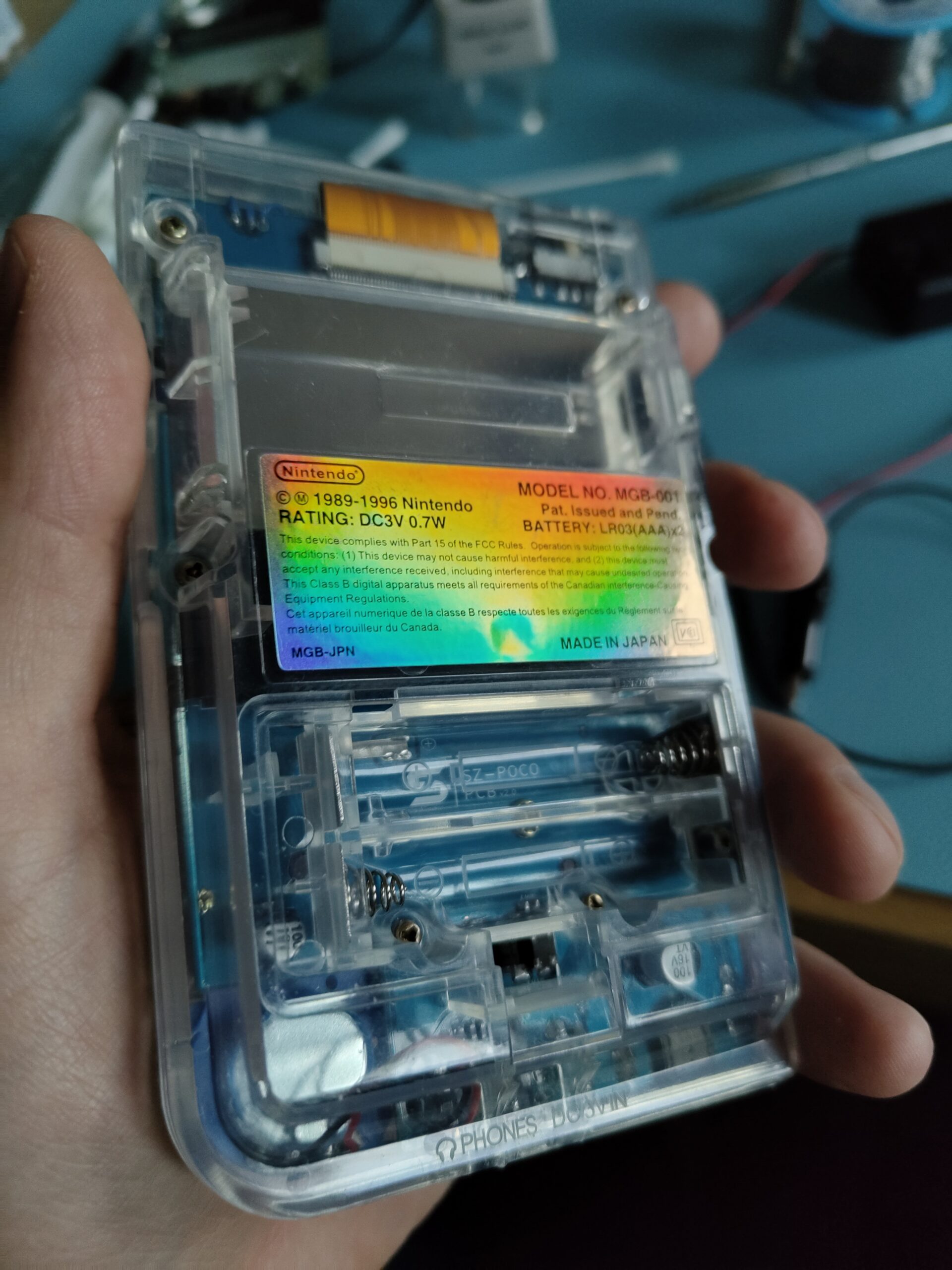
I assemble it all together again and after testing it out for some days it seems to be solid now. I put the final touch on it by applying a holographic GBP sticker on the back.
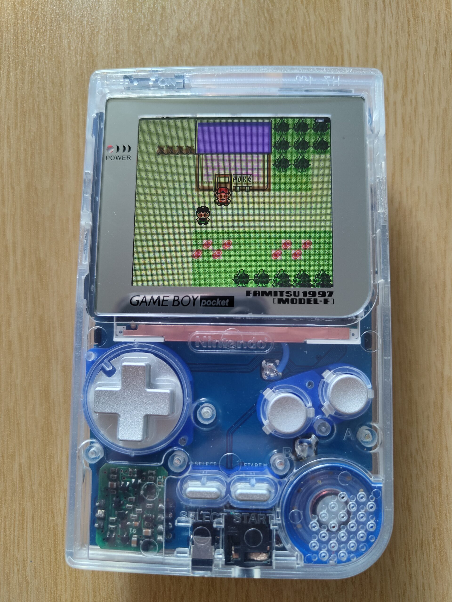
At some point during the opening and screwing it back together again I must have tightened the left screw holding the PCB to the front shell a bit too tightly because it has developed a crack there now as can be seen in the final photo. But I don’t even care. It’s a beauty. I have untightened the screws slightly to prevent it from getting worse at least.
All in all this project probably took me something like 15-20h to put together with all the troubleshooting I had to do. But I think it was worth it in the end.
Final thoughts
This was a major undertaking for me. Not only my first real project with surface mount components but also the biggest. One of the reasons I wanted to do it was to push my skills to the next level. It took me a long time to put together, and I ran into some issues, but I learned so much along the way. It was a lot of fun (for the most part haha) and it was very satisfying to see it boot up properly the first time. Kudos to skimzor for putting together such a nicely designed PCB. And thanks to all the awesome people on the Gameboy Discord server for helping me. I will revisit this in the future once I get myself a decent hot plate and liquid solder to attempt another build of the custom regulator board, but for now the stock one will do.
The one major con to this mod is that the original GBP uses AAA batteries. With this IPS screen the battery life takes a major hit. With normal alkaline batteries I’ve measured the battery life to be about 3h using a standard game cartridge at the lowest screen brightness, which is still bright enough in my opinion. 3h is pretty decent I think, but add a flashcart to that and it will be even less. For serious gaming with a flash cartridge perhaps a DMGC is a better solution… Stay tuned!
Links
- skimzor’s ko-fi page – Where you can buy the SZ-POCO PCB.
- Retro Game Repair Shop – For various GB aftermarket parts, including the screen, buttons, button membranes, speaker and the sticker I used.
- Cloud Game Store – For the clear shell.
- Makho’s screen brackets – For the screen alignment bracket. I went with the FP_DMMG_IPS_Bracket.kicad_pcb one.
- Makho’s Youtube channel – Has taught me so much about Game Boy mods and inspired me to have a go at this build myself.